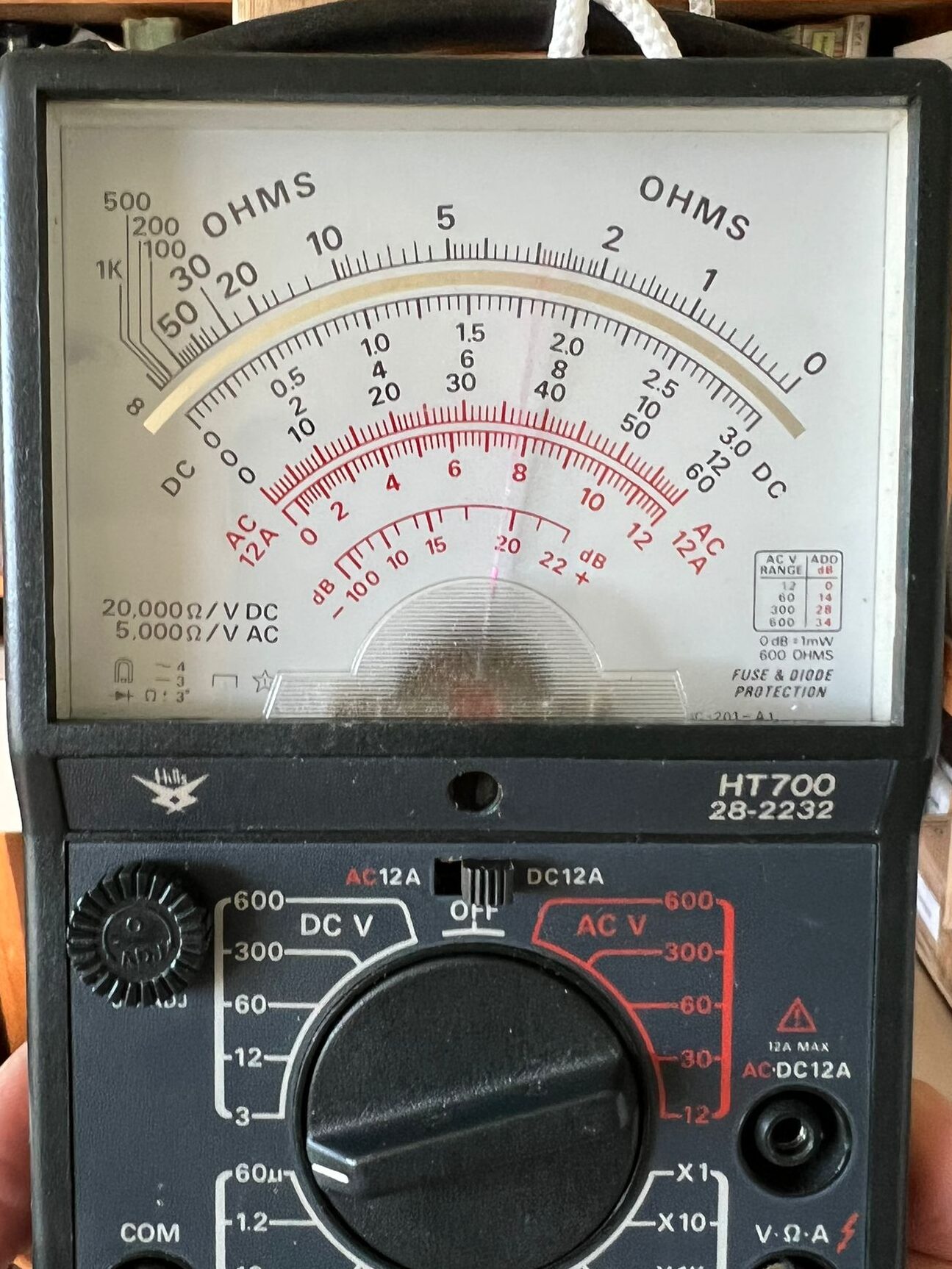
I bought couple of cheap meters, £3 each, at the 2022 Hamfest. It is fairly easy to add an RF current sensing loop inside the case of one of these meters, with rectifying diodes (1N34, Germanium), 1nF capacitances and 470R resistive padding. This is then internally connected to the 60uA range of the meter. It works, as shown below, as a broadband RF current sensor. It can be used to confirm that RF current is flowing in an antenna, so the antenna should radiate. The meter continues to work normally on the other ranges, so makes a handy shack test meter, with added RF capability.
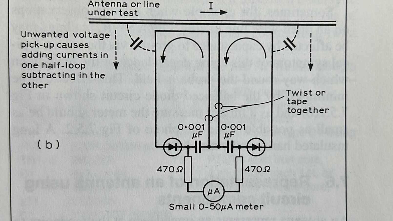
The selected meter is an HT700, which was sufficiently popular to be featured in some RSGB publications. The image well below shows a build of the probe design, as given in Test Equipment for the Radio Amateur by Clive Smith, G4FZH.
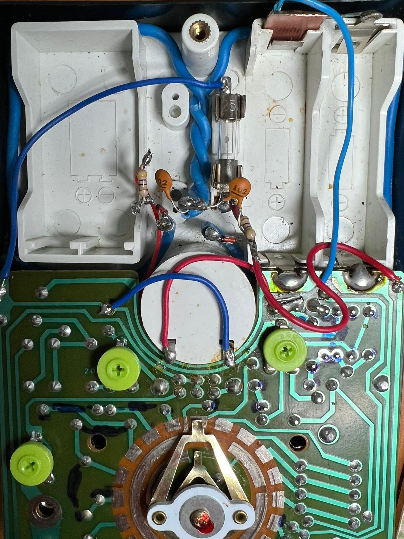


Note that this internal modification will only work with a meter with a case transparent to RF, so a traditional metal cased test meter, such as an AVO-8, would not be suitable. All is not lost, however, the sense electronics could be built in a separate plastic box, and the output leads connected to the 50uA input of the AVO using 4mm banana plug leads as a separate test head.
Basic soldering skills are required for this project. The sense loop pair, made from 2.5mm solid insulated copper, retrieved from electrical twin and earth, is mechanically strong. The two loops can be wrapped tightly in the centre using pliers and a bench vice, with care not to damage the insulation. The loops are then shaped around the rear of the meter movement housing, behind the battery compartment in the diagram, and brought back together just above the cylinder which houses the meter solenoid and magnets forming a double DD shape (see the diagram below). These wires are sufficiently sturdy to directly support a twist and solder fixing for the resistors, capacitors and diodes, as shown in the photographs, and given in the diagram below. A handheld 25w soldering iron with a small tip is find for this work. Be careful not to overhead the diodes, germanium does not survive overheating. Using a pair of pliers as a heatsink to protect the diodes is recommended for less experienced constructors.
The direction of connection of the capacitors and resistors is not important.
The direction of connection of the diodes is important. The black stripe on the diodes indicates the cathode end. The anode and cathode of a semiconductor diode are named to follow the convention of thermionic valve diodes, where 'an-' means 'upper', and '-ode' is short for electrode. 'An-ode' is thus the upper electrode of the valve drawn in the usual way, which is connected to the more positive side of the supply, HT, or B+. Electrode is based on the greek word Elektra, which means Amber, the substance first used to create static electricity.
For a diode, conventional current flows from the HT/ Battery+, through the Anode, to the Cathode inside the diode and then round to 0 volts, (aka chassis, ground, earth or B-). The arrow inside the diagram for the semiconductor diode shows the direction of conventional current, hence the arrow points from anode, to cathode, just like the flow of a traditional thermionic valve. The black stripe indicates the single bar in the diode diagram, the cathode end. This end must be more negative for current to flow through the diode.
The connections to the meter are also polarised. The positive side of the meter for the 60uA range goes to the resistor connected to a diode cathode. I found the connection for the 60uA range by tracing the connections from the meter terminals back to the rotary switch, and soldered the wire directly to the board. This can be seen as a red wire which goes to the bottom of the PCB, and then routes back up to the sense loop.
The negative side of the meter goes to the resistor connected to a diode anode, locating this is done by tracing the negative terminal back to the PCB. If these are connected the wrong way around, the sense loop electronics will try to deflect the meter the wrong way. On a small signal, this should not cause any lasting damage, but it should not be done with a large signal or repeatedly, or for an extended period, there is a risk of meter damage.
Having wired the components in, a great test is to hold the newly modified meter up close to an antenna and transmit! Don't forget to select the 60uA range, anything else will just work as normal, as it is not connected to the sense loop.
If the meter does deflect the wrong way, then swap the connection to the meter. Experience shows that you need to be close to the wire with RF in to sense it. The meter case physically touching is ideal. Holding the meter close to a coaxial feeder is unlikely to prove effective, although it may work on balanced feeder if the meter is close to one wire, and as far as possible from the other.
Consider that RF current usually has nodes, like voltage, in RF systems, so moving the sense loop to a different position on the antenna might find current flowing. At the end of a dipole, there should not be any current flowing, but there would be a voltage node, so careful placement of the loop is important for sensing.
In the picture below, the meter is help up close to a home-built loop antenna, main loop made from URM-67, with a copper driving loop pulled from 2.5mm twin and earth, and a recovered tuning capacitor, around 500pF.
The meter deflection is clear in the picture below on transmit, with about 5 watts of FT8 carrier into the loop. The amount of deflection is not calibrated, but the action of the tuning capacitor on the loop is clear. The tuning capacitor is adjusted for maximum deflection, but care must be taken to keep the meter a constant distance from the antenna.